164 Results
View results:
Sort by:
![Time-Dependent Settlement Components [2]](/en/webimage/009673/2419908/01-en-png-png.png?mw=640&hash=5e657e3feb5c1bb6d21727468dd85d91e1c9f29f)
For the serviceability limit state design according to Section 6.6 of Eurocode EN 1997‑1, settlement has to be calculated for spread foundations. RF-/FOUNDATION Pro allows you to perform the settlement calculation for a single foundation. For this, you can chose between an elastic and a solid foundation. By defining a soil profile, it is possible to consider several soil layers under the foundation base. The results of the settlement, foundation tilting, and vertical soil contact stress distribution are displayed graphically and in tables to provide a quick and clear overview of the calculation performed. In addition to the design of the foundation settlement in RF-/FOUNDATION Pro, the structural analysis determines the representative spring constants for the support and can be exported to the structural model of RFEM or RSTAB.
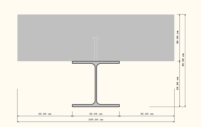
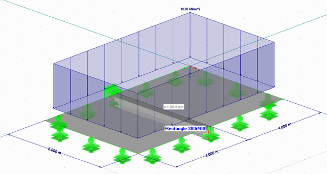
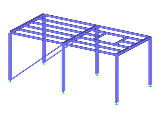
There are different options to model composite cross‑sections in RFEM. In the following example, three different modeling options for a composite cross‑section, consisting of a rolled steel section HEA 300 and a rectangular cross‑section made of concrete w/l = 100/30 cm will be displayed and explained.
When analyzing structural components of reinforced concrete structures, it is often necessary to design deep beams. These are mainly used for window and door lintels, upstand and downstand beams, the connection between split-level slabs, and frame systems. If they are displayed as surfaces in RFEM, the evaluation of reinforcement results requires further steps.
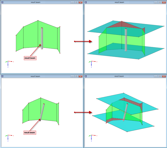
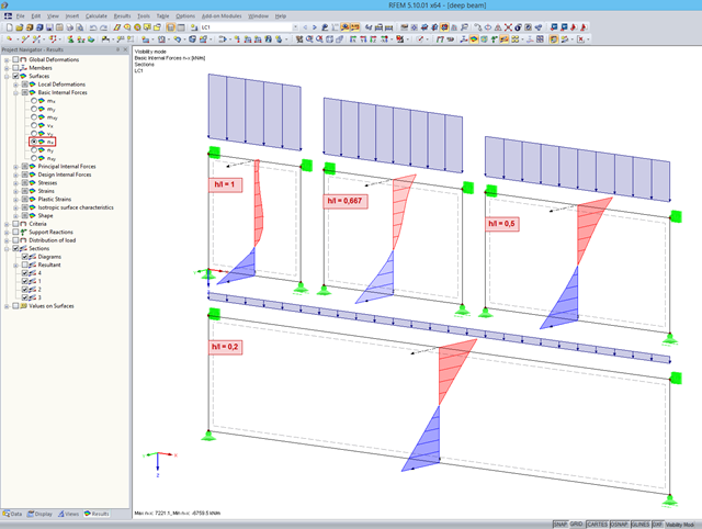
The "Result Beam" member type has been available since the release of RFEM 5. The result beam is a virtual member that does not have any stiffness nor require any support. It can be used in various situations in order to integrate the results from members, surfaces, and solids, and to display them as member internal forces.
![Tension Cover Line from [1]](/en/webimage/009390/2418541/01-en-png.png?mw=640&hash=c76563b459152b19c98197ea6ba342be89d9a5bc)
In the case of a large amount of reinforcement, it might be useful to grade the longitudinal reinforcement of a beam, which means: curtailment. The grading corresponds to the tensile force distribution. Using RF-CONCRETE Members and CONCRETE, you can specify the curtailment of the reinforcement, which is considered in the automatically proposed reinforcement for the longitudinal reinforcement. When determining this reinforcement proposal, it is necessary to ensure that the envelope of the acting tensile force can be absorbed.
![Reduction of Building to Cantilever Structure: The individual mass points represent the floors. The deflection due to the normal compression forces shown in (a) is (b) converted into equivalent moments of displacement or shear forces [2].](/en/webimage/009762/2420261/01-en-png-12-png.png?mw=640&hash=2753cb61c54a78756b34fd3ab03c92ed01b9fd39)
For the ultimate limit state design, EN 1998 1, Sections 2.2.2 and 4.4.2.2 [1], requires the calculation considering the second-order theory (P-Δ effect). This effect may be neglected only if the interstory drift sensitivity coefficient θ is less than 0.1. The coefficient θ is defined as follows:
$$\mathrm\theta\;=\;\frac{\displaystyle{\mathrm P}_\mathrm{tot}\;\cdot\;{\mathrm d}_\mathrm r }{{\mathrm V}_\mathrm{tot}\;\cdot\;\mathrm h}\;(1)$$
where
θ is the interstory drift sensitivity coefficient,
Ptot is the total gravity load at and above the story considered in the seismic design situation (see Expression 2),
dr is the design interstory drift, evaluated as the difference of the average lateral displacements dS at the top and bottom of the story under consideration; for this, the displacement is determined using the linear design response spectrum with q = 1.0,
Vtot is the total seismic story shear determined using the linear design response spectrum,
h is the interstory height.

In RF-STEEL Surfaces, it is possible to display the stresses relevant for the design of welds, for example, according to EN 1993‑1‑8, Figure 4.5. When evaluating the stress components, the local xyz-axis system of the surfaces must be considered.

RFEM and RSTAB offer different options to model bored piles. One option is to display bored piles as single-valued supports or hinged columns. Another option is realistic modeling while taking the soil into account by means of applying a member elastic foundation. The two following examples will describe it in detail. However, pile base resistance, skin friction, and soil layers are not considered in this technical article.
When performing control calculations and comparing the internal forces and the resulting required reinforcement of downstand beams, large differences can occur. Although the same load assumptions and spans are applied, some programs or the manual calculation display very different internal forces compared to the FEA model. The differences already occur in the case of the centric member and without considering the internal forces' components from the possible effective slab widths.
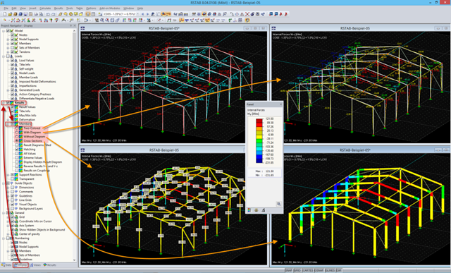
In the RFEM and RSTAB work window, four display modes are available for the results of members. They can be selected in the Display Navigator under "Results" → "Members".
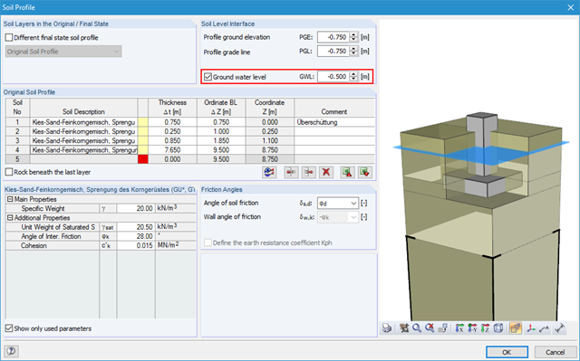
Using RF-/FOUNDATION Pro, it is possible to perform geotechnical design according to EN 1997‑1 [1] for single foundations. Subsequently, the program displays detailed information about the influence of the ground water level on the selected design according to EN 1997‑1.

Besides the standardized gamma method, you can display the semi-rigid composite beams also as a framework model.
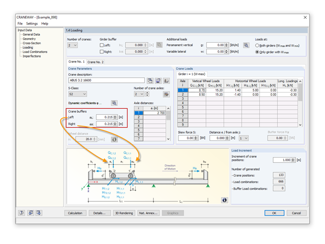
In the event of converting or extending a hall, the building owner may want to add a second or third crane to an existing crane runway. Since the original design usually does not consider other cranes, a common solution is to design a minimum distance between the cranes. This is done via the crane technology settings.

An FE mesh quality display is available in RFEM as a tool for structural analyses of two-dimensional components. It leads to the execution of an internal check of the generated finite elements for defined criteria.

You can model and analyze masonry structures in RFEM 6 with the Masonry Design add-on that employs the finite element method for the design. Complex masonry structures can be modeled, and static and dynamic analysis can be performed, given that a nonlinear material model is implemented in the program to display the load-bearing behavior of masonry and the different failure mechanisms. You can enter and model masonry structures directly in RFEM 6 and combine the masonry material model with all common RFEM add-ons. In other words, you can design entire building models in connection with masonry.
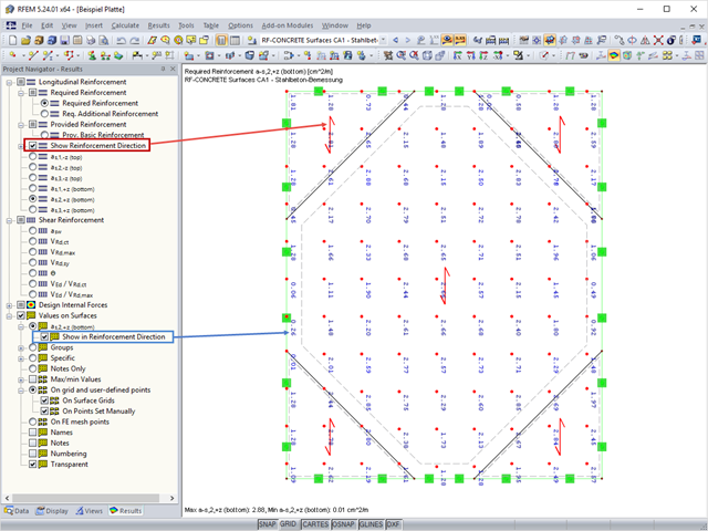
In RF‑CONCRETE Surfaces, the design of the surface reinforcement is done by means of a freely definable reinforcement mesh. In RF‑CONCRETE Surfaces, you can display the reinforcement direction by activating the reinforcement arrow that represents it.

In RFEM, you can display the contact properties between two surfaces by means of contact solids. Among other things, you should ensure that both contact surfaces of a contact solid have the same integrated objects. Therefore, when modeling the contact surfaces, we recommend using the copy function in order to create the second contact surface.

In RF‑/FOUNDATION Pro, the reinforcement to be placed in the foundation slab and, if necessary, the bucket links, is displayed in a 3D rendering and in the reinforcement drawings.

For a quick overview of the cross‑sections used, you can show the members in color sorted by cross‑section. Use the right mouse button in the work window to select "Colors in Graphics According to" → "Cross -Sections" from the shortcut menu. In the current program versions, you can use a panel with an editable color scale for this.
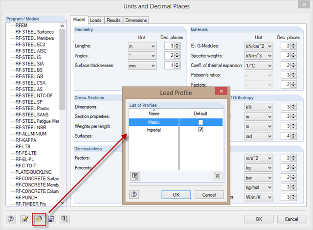
When changing the units from the metric to the imperial measurement system, it is not necessary to change all the units individually. To do this, corresponding unit profiles are available in the "Units and Decimal Places" dialog box, which you can activate as shown in the picture.
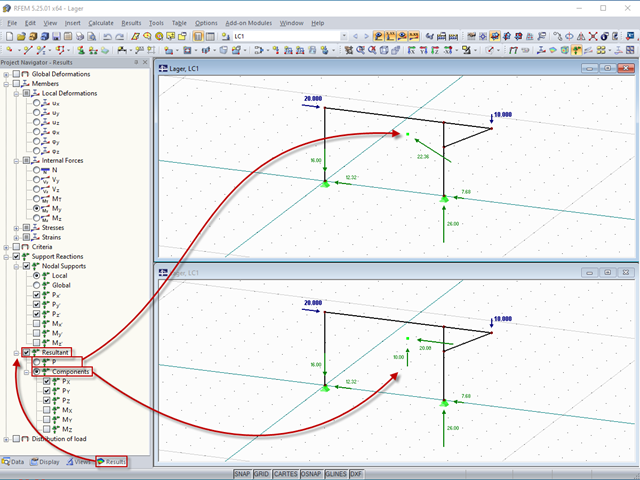
In RFEM 5 and RSTAB 8, you can display the resulting support force related to the centroid of the model. It can be used, for example, to check the model and load data.

Both the determination of natural vibrations and the response spectrum analysis are always performed on a linear system. If nonlinearities exist in the system, they are linearized and thus not taken into account. Straight tension members are very often used in practice. This article will show how you can display them approximately correctly in a dynamic analysis.
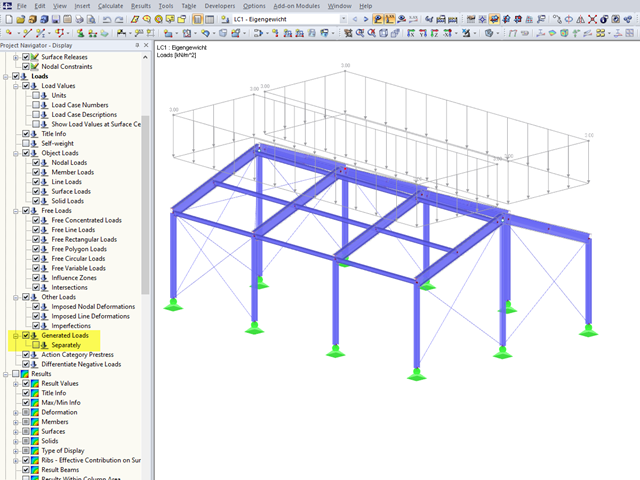
In RFEM 5 and RSTAB 8, you can generate surface loads like wind and snow by means of the implemented load generator. On frameworks, these surface loads are also displayed as surface loads in the graphic by default.
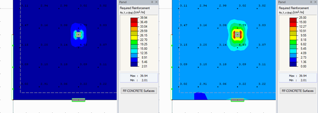
RFEM offers different options for the graphical display of results that have been determined in RF-CONCRETE Surfaces. This article gives an overview of these options.
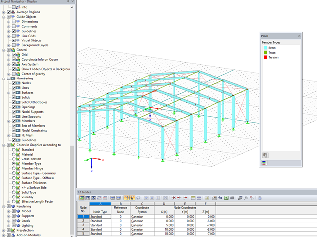
In RFEM and RSTAB, you can now also display and check the types of members used visually, by means of colors. To do this, an option has been integrated into the Display Navigator.
The steady state for periodically excited structures can be determined by means of the modal analysis in the DYNAM Pro - Forced Vibrations add-on module. This is an advantage if only the structure's steady state is of interest. Instead of a complete solution of the equation of motion, only a special solution is displayed.

When evaluating line support forces, implausible diagrams sometimes arise at first glance. In particular, for variable loads at locations that also have a nodal support, at division points and edge locations of supported lines, the results sometimes show unexpected support reactions. Using the function of the linear smooth distribution in Project Navigator – Display does not always lead to the expected result diagram.

You can make various settings in order to achieve a clearly‑arranged display of the result values. For example, some users may not want the white background in text bubbles. You can adjust the background in "Display Properties" using the Transparent and Background color option.
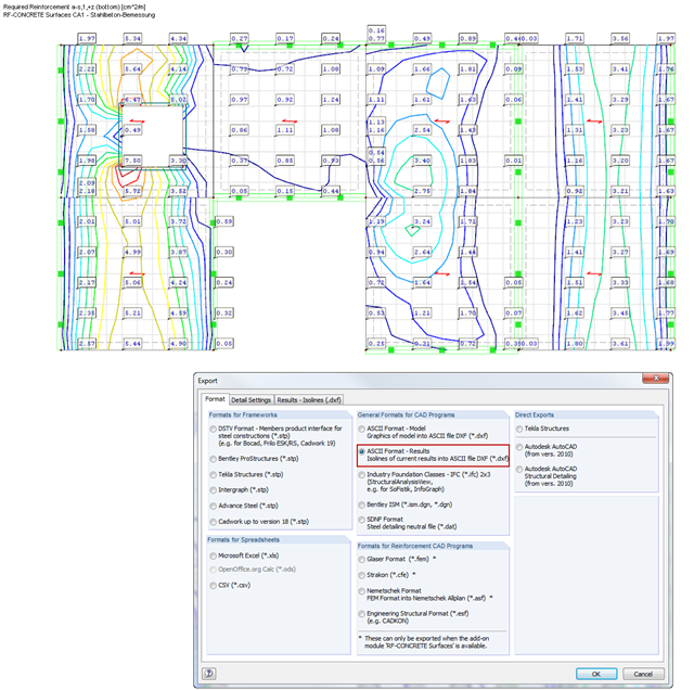
RF‑CONCRETE Surfaces performs the ultimate and the serviceability limit state design of slabs, plates, folded plates, and shells. In RFEM 5, the reinforcement resulting from this design can be displayed graphically on the surfaces of the structure using isolines. For the reinforcement design, it may be useful to export the results as isoline distribution in a DXF file in order to open them in a CAD application as background layers.

In RF‑/FOUNDATION Pro, reinforcement drawings are displayed after designing the foundation, where you can record all necessary structures of the reinforcement steel.